Use our convenient Google search bar below to find anything relating to this website.
Custom Search
Our Impala project is now complete. Scroll down this page for the latest design we have created for this show piece.
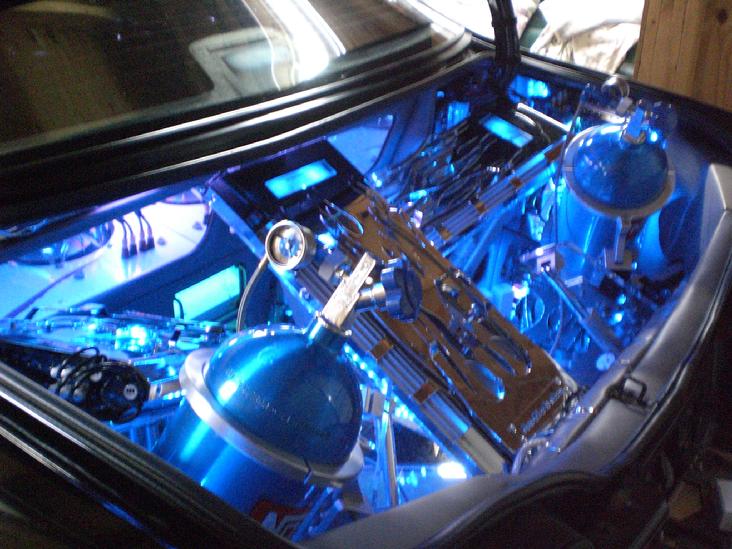
What!! Something from the movie Transformers? Nah, that's just our trunk.
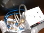
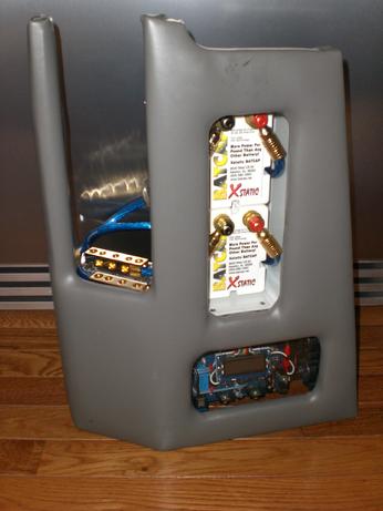
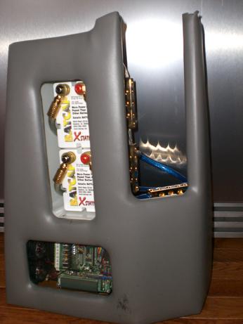
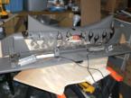
This is one of the side walls that houses a set of XStatic BatCap Batteries and the distribution blocks for the amplifiers and electronics in the trunk.
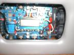
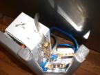
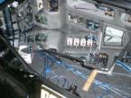
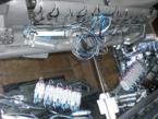
Above, is the Fan Thermostat Control and Switching Turn-On Control Unit All in one. Basically, this unit controls the fans by temperature to the motorization computer and amplifiers. The unit also has 6 channels for remote turn on by the use of mosfet technology. I simply designed all the components on a motherboard and eliminated the use of external relays for individual switching on and off. Specially for those days at the car show when you would like to adjust one amplifier at a time this really comes in handy. The switch control for this is located on the front underneath the radio.
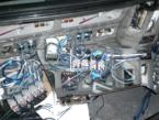
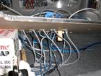
Now, let's take a look at this very closely. This unit along with the Thermostat control were built by scratch utilizing SMT technology and transistors. Both boards were built by hand. This unit above has a computer running a 360Mhz processor and 16Megs of Ram. This was not an easy process to accomplish. The design took about six to eight months and the build took another four months. YES, a whole entire year just to get it right! This unit controls the motorization of the trunk components. It has fifteen channel outputs. Eight of the fifteen channels are controlled by external pulse relays and the rest are controlled by high power mosfets located on the board that can drive about fifteen amps each. The unit uses a C++ program to control each of the outputs. The program can be easily modified by using an RS-232 port built onto the board.
Here we put our mini computer to use. View the videos below so you can see some crazy motorization with just the push of the trunk release button on the car alarm remote. Clearly one of the most insane projects from Jtronx profressionals!!!
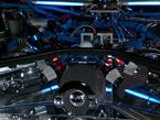
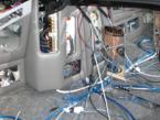
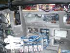
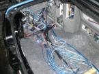
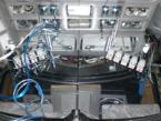
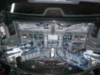
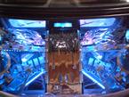
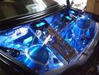
Snapshots of the trunk components. First glimpse of Two Nitrous Bottles, LCD Screens, lots of mirror, strobes, blue neon, Amplifiers, Amplifiers and more Amplifiers........
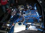
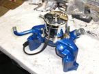
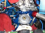
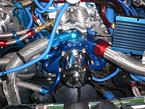
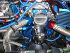
Well, the water pump went. So, I decided to replace the original water pump with a high performance part. Why not add a couple more ponies while I'm at it. I decided to go with a Heavy Duty Meziere Water Pump from Meziere Enterprises. This puppy is a heavy duty unit which flows 45 gpm, that's anough gallons to keep the SS nice and cool. I went ahead and purchased an OEM water pump housing and I capped off the center pump hole with a plug and glued it down with some heavy duty weld epoxy. Then I painted the housing to match the engine parts. Nice!!!
After installing the pump I had to wire the electrical connection from the pump to a relay. This relay is wired to a cut-off switch on the gauge pillar inside the car. A bi-color LED lights up Blue when the ignition is On indicating the pump is running. When I switch the cut-off switch to the Off position the bi-color LED lights up Red indicating the pump is Off. This is great when the car is not running and the ignition is on while working on the car the battery will not go dead.
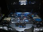
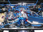
Final results of the engine compartment. Looks very nice and clean. Future modifications include aluminum coolant reservoir tank and an oil catch tank. But, this will do for now .
Any inquiries please contact us at sales@jtronx.comand ask for JR
Jtronx™ Custom Car Audio Alarm and Performance. All rights reserved. All images and info within this site are copyright of Jtronx™ Custom Car Audio Alarm and Performance. 2004-2009


 .
.